
Diagnosing Compressor Failures: Step-by-Step for HVAC Techs
Compressor failures remain one of the most critical and costly issues HVAC technicians face. According to the Air Conditioning Contractors of America (ACCA), compressor malfunction accounts for nearly 30% of major system failures, often leading to expensive repairs or full system replacements. A structured, methodical approach to diagnosing these failures not only saves time but also protects the technician’s reputation and customer satisfaction. This guide walks HVAC techs through the essential steps to accurately identify compressor problems with confidence.
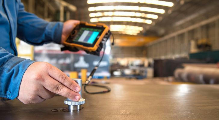
Step 1: Preliminary Visual and Sound Inspection
Before diving into complex diagnostics, begin with a thorough visual and auditory inspection. A U.S. Department of Energy study highlights that over 40% of compressor failures show early warning signs detectable by sight or sound.
Key checks include:
- Listening for abnormal noises such as clanking, humming, or rattling, which can indicate mechanical wear or electrical issues.
- Inspecting the compressor housing for oil leaks, corrosion, or physical damage.
- Checking electrical connections for signs of overheating or burning.
An attentive initial inspection can often reveal simple issues such as loose wiring or refrigerant leaks, which can masquerade as compressor failure.
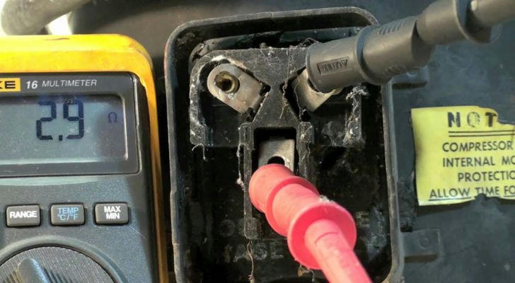
Step 2: Verify Power Supply and Electrical Components
Electrical faults are a leading cause of compressor failure. The National Fire Protection Association (NFPA) reports that improper wiring or capacitor failures contribute to thousands of HVAC-related fires annually.
Perform these tests:
- Use a multimeter to measure voltage supply at the compressor terminals; verify it matches manufacturer specifications (typically 208-230V).
- Test capacitors (start and run capacitors) using a capacitance meter; replace if values deviate beyond ±6% of rated capacity.
- Inspect the contactor and overload relay for continuity and mechanical wear.
Ensuring proper and stable power delivery is critical; intermittent voltage or faulty components can prematurely damage compressors.
Step 3: Assess Refrigerant Charge and System Pressure
Incorrect refrigerant levels can lead to compressor overheating or inefficient operation. According to EPA Section 608 regulations, refrigerant handling requires certified technicians, ensuring safe and legal practices.
Testing involves:
- Connecting manifold gauges to measure high- and low-side pressures under running conditions.
- Comparing pressure readings against manufacturer’s performance charts for the specific system and ambient conditions.
- Checking for signs of refrigerant leaks with electronic leak detectors or UV dye inspection.
Low refrigerant levels often cause compressor short cycling, while overcharging can lead to excessive pressure and mechanical stress.
Step 4: Evaluate Compressor Windings and Insulation
Internal electrical faults within the compressor motor windings are common failure points. ASHRAE guidelines recommend insulation resistance testing to identify these issues early.
Use a megohmmeter (megger) to:
- Test winding insulation resistance between compressor terminals and ground; values below 1 megaohm typically indicate degradation or shorts.
- Perform resistance measurements of start, run, and common windings to detect open circuits or imbalances.
Faulty windings can cause the compressor to draw excessive current, triggering overload protection and eventual failure.
Step 5: Measure Compressor Current Draw
Monitoring current draw during operation provides insight into compressor health. The Electrical Apparatus Service Association (EASA) notes that abnormal amperage often precedes catastrophic failures.
Use a clamp ammeter to:
- Compare running amps against manufacturer’s nameplate ratings and operational norms.
- Identify signs of locked rotors, phase loss, or mechanical binding by unusually high or low current.
- Observe starting current; excessively high values may indicate worn bearings or electrical shorts.
Anomalies in current draw help pinpoint whether the problem is mechanical or electrical, guiding further inspection or replacement.
Step 6: Check for Mechanical Problems Inside the Compressor
Mechanical failures such as broken valves, damaged pistons, or seized bearings usually require compressor replacement. However, a preliminary diagnosis can confirm the root cause.
Diagnostic actions:
- Listen for unusual noises indicating internal component failure.
- Attempt a manual rotation of the shaft (if accessible and safe) to detect seizing or roughness.
- Review oil quality and level inside the compressor; contaminated or low oil can accelerate wear.
Documenting mechanical issues early prevents unnecessary parts replacement and reduces labor time.
Step 7: Confirm System Controls and Safety Devices
Compressor shutdowns may be triggered by faulty sensors or safety controls rather than the compressor itself. Check these to avoid misdiagnosis.
Inspect:
- Pressure switches for correct operation and calibration.
- High-limit controls and thermal protectors for proper reset function.
- Control board fault codes and history for any related compressor lockouts or overload events.
Ensuring control devices function properly preserves compressor life and maintains system reliability.
Conclusion: A Methodical Approach Saves Time and Cost
Diagnosing compressor failures requires a blend of electrical, mechanical, and refrigerant system knowledge. By following these step-by-step procedures, HVAC technicians can reduce unnecessary part replacements, minimize downtime, and enhance customer trust. Leveraging manufacturer manuals, industry standards such as ACCA and ASHRAE guidelines, and using calibrated diagnostic tools ensures accuracy and professionalism.
Proactive maintenance, accurate diagnosis, and adherence to safety and environmental regulations are the keys to mastering compressor troubleshooting and delivering lasting solutions in HVAC service.